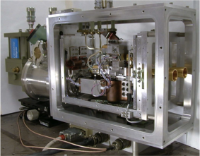
Redshift Search Receiver (RSR), the first-light wide-band 3 mm spectrograph currently installed on the LMT.
The Redshift Search Receiver (RSR) is a novel MMIC-based receiver (Erickson et al. 2007, ASP Conf. Series) designed to maximize the instantaneous receiver bandwidth to cover the 3mm wavelength atmospheric window (73-111 GHz) in a single tuning. The receiver has four pixels arranged in a dual-beam, dual polarized configuration (see Figures 1 and 2). Orthogonal polarizations are combined in waveguide-based orthomode transducers. Beam-switching at 1 kHz on the sky is achieved with a fast Faraday rotation polarization switch and a wire-grid to interchange the reflected and transmitted beams to each receiver (see Figure 1).

Figure 1: Block diagram view showing two beams on the sky. The orthogonal polarizations from both spots on the sky (see Figure 2) makes its way to 4 separate receiver outputs, and four independent spectral backends that produce 4 independent switched spectra that can be averaged together.
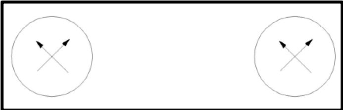
Figure 2: Beams are separated on the sky by ~78″ (~ 5 times HPBW). At any given instant, as the 1 kHz beam switch changes sign, the two orthogonal polarizations in each beam is received by four independent pixels. For more extended sources, there is a wide throw option which creates a spacing of 294″ between the beams.
This ultra-wideband receiver typically achieves noise temperatures < 50K between 73-111 GHz. Because of the fast beam-switch involving no moving mechanical parts, the Redshift Search Receiver has exceptional baseline stability, well-suited to the detection of redshifted transitions of the CO ladder from star-forming galaxies at cosmological distances. A innovative wideband analog autocorrelator system which covers the full 38 GHz with 31 MHz (100 km/s at 90 GHz) resolution serves as the backend spectrometer. The 38 GHz of total bandwidth is analyzed in 6 different slightly overlapping frequency bands (see Figure 3). Table 1 shows the salient characteristics of the RSR system. The RSR was commissioned on the FCRAO 14-m telescope in 2006, and in June 2011 it conducted the first-light scientific demonstration observations of the LMT.

Figure 3: The six different frequency bands of the RSR. Each band which is ~6.7 GHz wide is handled by a separate analog auto-correlation card. Four separate chassis handle the entire 38 GHz from each of the four RSR pixels.
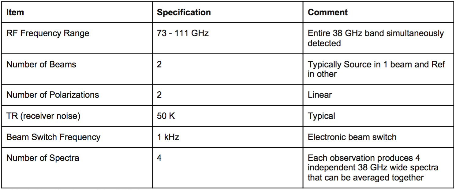
Table 1: Specifications of the RSR System.
Relevant information to be considered when requesting observing time with the RSR can be found it the RSR Observing Summary. RSR sensitivity and integration-time calculators, which consider the latest values of surface accuracy and efficiency of the 50m primary surface, are also available in LMT-Hedwig, the LMT’s proposal submission system.
A joint project of the Instituto Nacional de Astrofísica, Óptica y Electrónica and the University of Massachusetts.
The LMT is included in CONACYT's National Laboratories network.
All rigths reserved © Large Millimeter Telescope.


